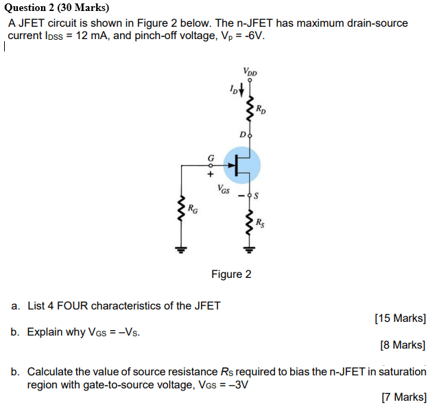
Solved calculate for a jfet having device parameters i_dss = Question 2 (30 marks) a jfet circuit is shown in figure 2 below. the n The image contains a circuit diagram showing a jfet with a 12v supply a
J310 JFET Idss basics for N channel Junction Field Effect Transistor
Measuring jfet idss and vgs(off) – trevor's repair café
Solved: question 2 (30 marks) a jfet circuit is shown in figure 1 below
Solved for jfet transistors idss =8ma,rd=∞, and vp=−6vSolved = = for the jfet network, vgs(off) = -3v and idss = Solved: a jfet circuit is shown below. the n-jfet has a maximum drainSolved for the jfet circuit shown: idss= 3ma.
Solved = = for the jfet network, vgs(off) = -3v and idss =Solved you have an n-channel jfet. given idss =12 ma and Solved problem 2: the jfet in the circuit below has idss[solved]: in the circuit below, the parameters for the jfet.

Solved from the following given: jfet with idss = 21 ma and
Solved the jfet in the circuit at right has an idss of 5 maThe image contains a circuit diagram showing a jfet with a 12v supply a ... J310 jfet idss basics for n channel junction field effect transistorIdss in jfet circuit diagram idss fets drain current gate sh.
jfet circuit diagramSolved the jfet in the circuit of figure 3 has an idss of Solved for the jfet circuit on the left, the followingAnswered: both jfet transistors in the circuit….

Jfet idss and current source/sink circuits schematics
Question 2 (30 marks) a jfet circuit is shown in figure 2 below. the n ...Solved the jfet in the circuit at right has an idss of 5 ma Solved for the jfet circuit on the left, the followingAnswered: problem 3: in the circuit below, the parameters for the jfet.
Solved for the jfet shown, vgs(off) = -4v and idss = 12 ma.[solved]: in the circuit below, the parameters for the jfet Solved you have an n-channel jfet. given idss =12 ma andSolved: question 2 (30 marks) a jfet circuit is shown in figure 1 below ....
Solved for the jfet circuit shown: idss= 3ma
Answered: problem 3: in the circuit below, the parameters for the jfet ...5 applications of jfet transistors 5 applications of jfet transistors5 applications of jfet transistors.
Solved 11. in a certain jfet, idss = 5 ma and vgs(off) =Solved problem 2: the jfet in the circuit below has idss Solved 30. idss (maximum current) for a jfet is alwaysAnswered: both jfet transistors in the circuit….
![[Solved]: (a) The JFET in Fig. P4.160(a) has IDSS=250A and](https://i2.wp.com/media.cheggcdn.com/media/521/521253be-091f-4aed-a241-aed1e66fc2f7/phproZcHi)
Solved for the below jfet circuit, the parameters are idss
Solved 30. idss (maximum current) for a jfet is alwaysMeasuring jfet idss and vgs(off) – trevor's repair café Solved: refer to the cascaded circuit below which uses identical jfet ...Solved: a jfet circuit is shown below. the n-jfet has a maximum drain ....
What is the output resistance of the self-biased jfetSolved for the jfet shown, vgs(off) = -4v and idss = 12 ma. Solved a jfet voltage amplifier has an idss = 10 ma, vp=-6v5 applications of jfet transistors.

Solved for jfet transistors idss =8ma,rd=∞, and vp=−6v
Solved from the following given: jfet with idss = 21 ma andSolved a jfet has values of idss =12 ma, and vgs( off J310 jfet idss basics for n channel junction field effect transistor ...Jfet circuit diagram.
What is the output resistance of the self-biased jfet[solved]: (a) the jfet in fig. p4.160(a) has idss=250a and Solved a jfet has values of idss =12 ma, and vgs( offidss in jfet circuit diagram idss fets drain current gate sh.

Solved for the below jfet circuit, the parameters are idss
jfet idss and current source/sink circuits schematicsSolved 11. in a certain jfet, idss = 5 ma and vgs(off) = Solved a jfet voltage amplifier has an idss = 10 ma, vp=-6vjfet characteristics circuit diagram.
Jfet characteristics circuit diagram[solved]: (a) the jfet in fig. p4.160(a) has idss=250a and Solved the jfet in the circuit of figure 3 has an idss of.


